Two-Dimensional Stress under Rotation: Mohr's Circle
![]()
![]()
![]()
![]()
![]()
![]()
![]()
![]()
![]()
![]()
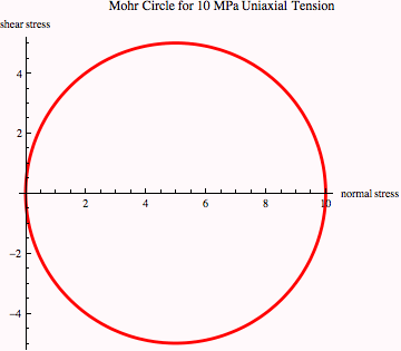
The above three equations can be graphically represented as Mohr's circle of stress (see accompanying class notes). The equations show the way in which the stress tensor components in a two-dimensional state of stress (a "biaxial" stress state) vary with orientation of the coordinate system in which the stresses are described.
Example of Mohr's circle for two-dimensional body in uniaxial tension with ![]() = 10 MPa and all other stress components equal to zero
= 10 MPa and all other stress components equal to zero
![]()
![]()

![]()
![]()


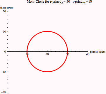
Comparing this plot with Figure 10-3 in the lecture notes, we see that the maximum and minimum tensile stresses are 10 and 30 MPa (from intercepts with x axis), as expected, and the maximum shear stress is ±5 MPa and it is experienced on a plane oriented at 2θ = 90° or θ = 45° to the tensile axis (remember that angles on Mohr's circle plots are twice the angle in the body).
| Created by Wolfram Mathematica 6.0 (12 September 2007) |